Peripheral Devices
Overview
The purpose of the peripheral devices modeled here is to include a bare minimum set of devices that make the model realistic, and sufficient to port a basic operating system on top of it.
- Timer
A countdown timer, used for generating periodic interrupts, the kind an OS uses for context switching. - Interrupt Controller
Arbitrates and delivers hardware interrupts to the core. - Serial Device
A single device for I/O.
The register formats, addresses, and behavior documented here are credited to the AJIT processor documentation, Chapter 8, "Basic peripherals available for AJIT systems". The device models in this project are designed to be compatible with it, except for the deviations listed at the end of this page.
Connection diagram
A programmer's view of how the devices connect.
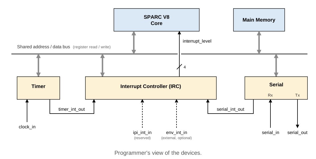
Every device has device registers that can be read and written over the same shared address/data bus the core uses for main memory. Each device also has its own individual signal pins, unrelated to the bus:
- Timer: a
clock_ininput, and atimer_int_outoutput to the Interrupt Controller. - Serial Device:
serial_in/serial_outpins, and aserial_int_outoutput to the Interrupt Controller. - Interrupt Controller:
timer_int_out/serial_int_outinputs, two further reserved inputs (ipi_int_in, for a future multi-core extension, andenv_int_in, for an external interrupt source not modeled by any device here), and oneinterrupt_leveloutput to the core.
Device address map
All addresses are doubleword-aligned. Both lda/sta with the MMU
bypass ASI (0x20, see Appendix I of the SPARC V8 manual) and an
ordinary translated access work, since device pages are identity
mapped.
| Device : Register | Address | Access type | Instruction example |
|---|---|---|---|
| Interrupt Controller : Control | 0xFFFF3000 |
word (32-bit) | sta %rs, [%rd] 0x20 |
| Timer : Control | 0xFFFF3100 |
word (32-bit) | sta %rs, [%rd] 0x20 |
| Serial : Control | 0xFFFF3200 |
word (32-bit) | sta %rs, [%rd] 0x20 |
| Serial : Baud limit / baud control | 0xFFFF320c |
word (32-bit) | sta %rs, [%rd] 0x20 |
| Serial : Tx | 0xFFFF3210 |
byte (8-bit) | stub %rs, [%rd] 0x20 |
| Serial : Baud frequency | 0xFFFF3210 (shared with Tx, see note) |
word (32-bit) | sta %rs, [%rd] 0x20 |
| Serial : Rx | 0xFFFF3220 |
byte (8-bit) | ldub [%rd] 0x20, %rs |
%rd holds the register's address, loaded with set beforehand.
Tx and baud-frequency share an address
The Serial Device's Tx register and its baud-frequency register
are both mapped to 0xFFFF3210. They are distinguished by access
width, not address: a byte-width access (stub) writes a
character to Tx, a word-width access (sta) writes the
baud-frequency register. This is intentional sharing of an
address, not an error. See the Serial Device page for the
baud-rate register format.
Interrupt levels
| Source | IRL | Priority |
|---|---|---|
| Timer | 10 | Highest |
| IPI (reserved for a future multi-core extension) | 11 | |
| Serial | 12 | |
| Env (external, not modeled by any device here) | 14 | Lowest |
The per-core Interrupt Controller priority-encodes its active, unmasked sources by IRL: the lowest IRL number among them wins. See the Interrupt Controller page for the masking behavior.
Deviations from the AJIT Processor
None yet. This section will be populated as deviations are introduced during implementation.