Interrupt Controller
A per-core Interrupt Controller (IRC). Each core has its own instance:
its own control register, its own state, and its own interrupt_level
output pin to that core. It has four interrupt input pins, and
communicates with the core over the shared address/data bus through
its control register, accessed with word load/stores only. See
Peripheral Devices for the connection diagram
and the full address map.
Interrupt sources
| Pin | Source | IRL | Status here |
|---|---|---|---|
timer_int_out |
Timer | 10 | Modeled |
ipi_int_in |
A future multi-core orchestrator | 11 | Reserved, unconnected |
serial_int_out |
Serial Device | 12 | Modeled |
env_int_in |
An external interrupt source, not modeled by any device here | 14 | Reserved, may be tied to zero or connected to a future external-interrupt-source model |
Control register
The mask field's bit positions match each source's own IRL, the same convention used to encode the active-interrupt vector: masking a source is a plain bitwise AND between the two.
| Bits | Field | Description |
|---|---|---|
[0] |
Enable | Writing 1 enables the IRC. Writing 0 disables it and clears interrupt_level. |
[10] |
Timer mask | If set, the Timer's interrupt is recognized. |
[11] |
IPI mask | Reserved. If set, a pending IPI is recognized (unused until a multi-core orchestrator exists). |
[12] |
Serial mask | If set, the Serial Device's interrupt is recognized. |
[14] |
Env mask | If set, the Env pin's interrupt is recognized. |
| all other bits | Reserved | Unused. |
On a register read, the format above (excluding bit 0) is echoed back as the currently active, unmasked interrupt sources, not the mask itself, letting software distinguish "masked but idle" from "active."
Priority
When more than one unmasked source is active at once, the IRC picks the lowest IRL number: Timer (10) > IPI (11) > Serial (12) > Env (14).
Behavior
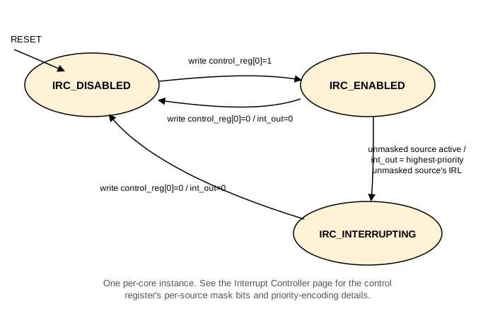
IRC_DISABLED
The reset state.interrupt_levelis 0. A write of the enable bit moves toIRC_ENABLED.IRC_ENABLED
Watches the four input pins. As soon as any unmasked source is active,interrupt_levelis set to that source's IRL (the highest-priority one, if more than one is active at once), and the IRC moves toIRC_INTERRUPTING.IRC_INTERRUPTING
interrupt_levelstays asserted until the CPU disables the IRC.
A write that clears the enable bit, from any state, immediately clears
interrupt_level and moves to IRC_DISABLED.
A future multi-core extension
This page describes a per-core IRC, sufficient on its own for a
single-core system: the ipi_int_in pin is simply never driven, and
the IRC works exactly as described above.
A later multi-core extension is expected to add a separate, single
shared orchestrator instance (not modeled here), responsible for
chip-level interrupt mapping, masking, and control, and for the
inter-processor-interrupt (IPI) mechanism itself. Its output would
connect into each per-core IRC's ipi_int_in pin, the same way the Timer
and Serial Device connect today, not replace or wrap the per-core IRC
in any way. When that shared orchestrator is absent or disabled, each
core's IRC continues to operate entirely on its own, exactly as
described on this page.