Serial Device
A memory-mapped serial device (UART) that exchanges bytes between the
core and an external I/O device. It has serial_in/serial_out
pins, a serial_int_out output pin to the Interrupt
Controller (IRL 12), and
communicates with the core over the shared address/data bus through
its own set of registers. See Peripheral
Devices for the connection diagram and the
full address map.
A single instance is modeled. A self-tuning variant, which auto-detects baud rate from an initial calibration byte, is not used here.
Registers
| Register | Width | Access |
|---|---|---|
| Control | 32-bit | word only (ld/st) |
| Tx | 8-bit | byte only (ldub/stub) |
| Rx | 8-bit | byte only (ldub/stub) |
| Baud limit / baud control | 32-bit | word only |
| Baud frequency | 32-bit | word only, shares Tx's address (see note below) |
See Peripheral Devices for the address of each register.
Access width, not just address, must be respected
The control register must be accessed with word load/stores. Tx and Rx must be accessed with byte load/stores. This is not just a style convention: the same address is a byte access to Tx or a word access to the baud-frequency register, discriminated purely by access width. Using the wrong width does not just fail, it silently targets a different register.
Control register bit-fields
| Bit | Field | Description |
|---|---|---|
[0] |
Tx_en |
Transmit enable. |
[1] |
Rx_en |
Receive enable. |
[2] |
Rx_interrupt_enable |
If set, receiving a byte raises an interrupt. |
[3] |
Tx_full (read-only) |
Set once the CPU writes Tx, cleared once it is transmitted. |
[4] |
Rx_full (read-only) |
Set once a byte is received into Rx, cleared once the CPU reads it. |
[5] |
UART_reset |
Resets the UART. Present only in the newest of the source references consulted; three older ones mark this bit unused, so treat it as unconfirmed until cross-checked further. |
Baud rate
The baud-limit and baud-frequency registers are computed from a desired baud rate and clock frequency, from the GCD of 16 times the baud rate and the clock frequency:
gcd            = GCD(16 x baud_rate, clock_frequency)
baud_frequency = (16 x baud_rate) / gcd
baud_limit     = (clock_frequency / gcd) - baud_frequency
Behavior
The device is modeled by two independent state machines, transmit and receive, sharing the one control register above.
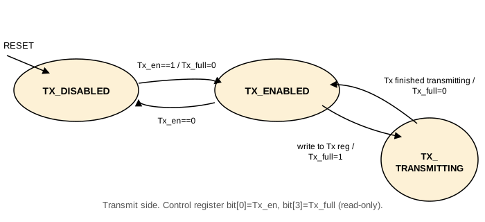
Transmit
TX_DISABLED
The reset state. A write ofTx_en=1clearsTx_fulland moves toTX_ENABLED.TX_ENABLED
Waits for a Tx register write. On one,Tx_fullis set and the device moves toTX_TRANSMITTING.TX_TRANSMITTING
Once the byte finishes transmitting,Tx_fullis cleared and the device returns toTX_ENABLED.
A write of Tx_en=0 from any state returns to TX_DISABLED.
To send a byte: enable the transmitter, write the byte to the Tx
register, then poll Tx_full until it clears before writing the next
one (or disable the transmitter).
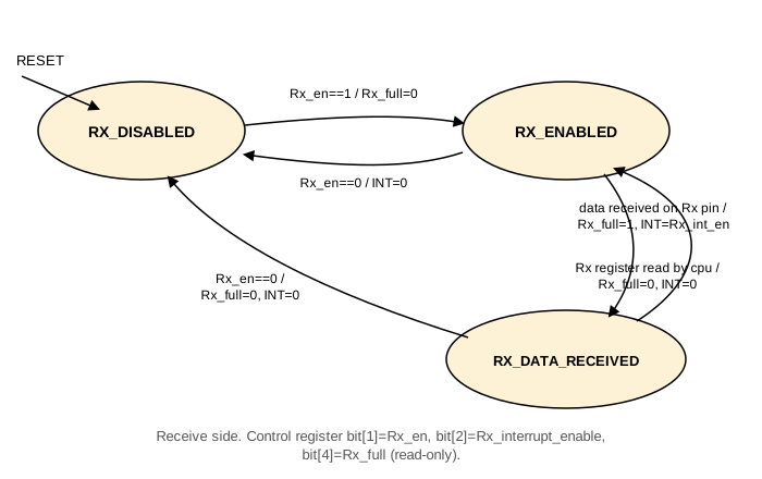
Receive
RX_DISABLED
The reset state. A write ofRx_en=1clearsRx_fulland moves toRX_ENABLED.RX_ENABLED
Waits for a byte on theserial_inpin. On one,Rx_fullis set, an interrupt is raised ifRx_interrupt_enableis set, and the device moves toRX_DATA_RECEIVED.RX_DATA_RECEIVED
Once the CPU reads the Rx register,Rx_fulland the interrupt are cleared and the device returns toRX_ENABLED.
A write of Rx_en=0 from any state clears Rx_full and the
interrupt, and returns to RX_DISABLED.
The receiver supports two usage modes, selected by Rx_interrupt_enable:
- Polling mode (
Rx_interrupt_enable=0): enable the receiver, pollRx_fulluntil it sets, then read the Rx register (and disable the receiver, or leave it enabled for the next byte). - Interrupt mode (
Rx_interrupt_enable=1): enable the receiver, wait for the interrupt, then read the Rx register (and disable the receiver, or leave it enabled for the next byte).