Timer
A simple countdown timer that operates only in one-shot mode. It has a
clock_in input pin, a timer_int_out output pin to the Interrupt
Controller, and
communicates with the core over the shared address/data bus through a
single control register, accessed with word load/stores only. See
Peripheral Devices for the connection diagram
and the full address map.
Control register
| Bits | Field | Description |
|---|---|---|
[0] |
Timer_en |
Enable bit. Writing 1 starts the countdown, writing 0 disables the timer. |
[31:1] |
Timer_max_count |
The value the count decrements from, set on the same write that enables the timer. |
Behavior
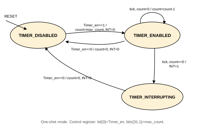
Software writes a maximum count into the control register and sets
the enable bit in the same write. From that point, the timer
decrements its count by one on every clock_in edge. When the count
reaches zero, the timer asserts its interrupt output (IRL 10, see
Peripheral Devices) and
stops counting. The interrupt output stays asserted until software
explicitly disables the timer.
TIMER_DISABLED
The reset state. The interrupt output is 0. A write ofTimer_en=1loads the count withTimer_max_countand moves toTIMER_ENABLED.TIMER_ENABLED
Counts down. The interrupt output is 0. When the count reaches 0, the interrupt output is asserted, and the timer moves toTIMER_INTERRUPTING.TIMER_INTERRUPTING
The timer stops counting. The interrupt output stays asserted until the CPU writesTimer_en=0, which clears it and returns the timer toTIMER_DISABLED.
A write of Timer_en=0 from any state immediately clears the count
and the interrupt output, and moves to TIMER_DISABLED.
Note
A free running 64-bit counter across ASR[31] and ASR[30], running at the processor clock and read-only, is documented separately from this Timer. It is unrelated to it, a CPU-internal cycle counter rather than a memory-mapped, software-configured countdown timer. Our Sitar model does not yet implement this counter.